FY810/820 Instruction Manual
Single/double needle post bed lockstitch sewing machine
- Post-bed design, suitable for shoes, handbags, leather products, etc.
- The full rotary horizontal shaft hook and the slide-type thread take-up lever, a well-tensed and beautiful finished seam is achieved with consistency
- Free feeding is possible with the roller presser
- The roller presser design is suitable to sew the abnormal material, such as various leather, sponge-within leather and light materials, which can keep the seam smooth and even, without crease
- Reverse stitching is available with an easy lever operation
- Easy to adjust the size of seam
- Changed roller presser foot to flat presser foot gauge set, so that can be suitable for hats and wigs sewing
- Double needles model of stable double row sewing has been realized, it’s up to 12.7mm in accordance with various size of gauge set

- Spool Pin
- Oil Reservoir (right)
- Balance Wheel
- Stitch Regulating Dial
- Reverse Lever
- Post
- Hook Post Holder
- Hook Post Cover Plate (back)
- Hook Shaft Bracket
10. Slide Plate 11. Needle Plate 12. Roller Foot 13. Thread Guide (needle bar) 14. Needle Bar 15. Thread Guide (needle bar bushing) 16. Presser Bar 17. Face Plate 18. Thread Tension Regular
19. Thread Guide 20. Thread Take Up Lever Guard 21. Presser Regulating Thumb Screw 22. Thread Take Up Lever 23. Thread Retainer 24. Oil Reservoir (left) 25. Pre-tension
Preparation for Installation of Machine Head

- Place of Installation of Machine: The machine should be installed on a well-level floor to ensure smooth operating of your machine at high speed without vibration.
- How to Mount the Machine Head on To the Table: Initial the hinge with screws, provided in accessory, at hole on the back of the bed and hook to the hinge plate of the table, then the head is set on the table.
- Mounting Of the Motor: The motor is mounted generally with bolts, nuts, and washers as provided. Set the position so that the motor pully and balance wheel grooves are aligned straight as shown in Fig. 1 (on left) For proper operation when the belt is settled. Then connect the power supply cord and motor cord extended from switch.
4. How to Connect the Motor Lever and Foot Pedal: The angle of the slope of the pedal can be important. It can make a difference in the strength necessary to press the pedal. There might be a slight difference in operator’s posture, but generally 30- 40 degrees angle as shown in Fig (A) is considered best. The treadle position shown in Fig (B) will be difficult. In this case, adjust the length of the connecting rod to suit the operator.
5. How to Mount the Bobbin Winder Assembly: Set the position of the bobbin winder assembly provided in accessory, to be in parallel with the belt hole of the table, with the lever pushed in operation position. When the bobbin winder pulley meets the belt, fix the assembly onto the table with two screws provided, as shown in Fig. (on right)

6. How to Mount and Adjust the Knee Lifter Mechanism: The knee lifter mechanism is employed to raise and lower the presser bar. Mount it properly onto the table by following method for easy operation. If improperly installed, the operating action will be heavy and tire the operator.
Make a hole for knee lifter shaft bracket underneath the table according to Fig. Shown (on Right)


- Mount the knee lifter shaft bracket while the side of the hole for spring towards your side as shown in Fig (on left)
- The other side of the knee lifter shaft bracket is screwed
- On the knee lifter shaft, mount the knee lifter position bracket, regulating rod bracket, knee plate bar bracket, and spring in the order mentioned, then tighten respectively.
- Mount the knee lifter shat, on which fixed respective parts, on the shaft bracket.
- After checking up all the parts and inclination of the knee lifter shaft, tighten the shaft bracket screws.

Adjustment
- Place of knee lifter position bracket: since the position bracket makes standardize the starting point of knee plate, tighten the screw at the proper position so that the stopper of position bracket come contact with top underneath of the shaft bracket (back)
- Position of the knee lifter bell crank regulating rod and its bracket.
- The regulating rod makes raise and down the presser foot by means of moving the bell crank lever up and down.
- While the presser foot downed, adjust the length (A) loosening the regulating rod screw so that the rod and crank lever contacts with as shown in Fig. (on Left)
7.HOW TO MOUNT THE OIL PAN Fit the oil pan with nails into the hole bored in the table, so as not to meet the knee lifter mechanism.
8. HOW TO MOUNT THE VIBRATION PREVENTING RUBBER The vibration preventing rubber is used to prevent the machine from vibrating and there by provide smooth operation of the machine. Fit these rubber insulators properly at the four corners of the table as shown in Fig. Remember, the machine will vibrate if these are not mounted properly.
- Hollow out four corners of the table 20mm radius and 13mm depth to fit the rubber insulators.
- Be sure to give smooth surface to “A” where hollow out is made.
- Nail the vibration preventing rubbers down at the four corners.

Preparation For Operation
1. SELECTION OF THREAD
- For best results, use high quality machine thread.
- For upper thread use left-twist thread.
- To check whether a thread is left-twist or right-twist, hold the thread as shown in Fig. and twist the thread held in the right hand toward your side. If the thread twist becomes loose, the thread is right-twist, and if the thread twist becomes tight the thread is left-twist

2. HOW TO ATTACH THE NEEDLE.
- Dpx5 (135×5) type needle is recommendable for general use.
- But select the needle size that meets the requirements of the materials sewn and the thread used.
For One Needle Type
- While the presser bar lifter is raised, turn the balance wheel by hand to raise the needle bar to its highest position.
- Move the roller foot to the left as shown in Fig.
- Loosen the needle clamping screw.
- Hold the needle to its side with the long groove side (left). Then insert the needle deeply it will go into the needle clamping hole.
- Securely tighten the needle clamping screw.

For Two Needle Type
- While the presser bar lifter is raised, turn the balance wheel by hand to raise the needle bar to its highest position.
- Move the roller foot to the left as shown in Fig.
- Loosen the needle clamping screw.
- Hold the needles so that the two needles side with the long grooved (faces each other) and insert it as deeply as it will go into the needle clamping holes. (5) Securely tighten the needle clamping screw.


When using nylon or silk threads, the loops may be formed improperly or stitch skipping may result due to the twist of these threads. In this case, observe the condition of the loops and mount the needle in a manner that the needle hole” would be positioned in a slightly oblique direction.
- HOW TO THREAD THE UPPER THREAD
For One Needle Type
- Raise the thread take up lever to its highest position turning the balance wheel by hand.
- After the presser bar lifter is raised, move the roller foot to the left holding downward as per arrow shown in Fig.
- Thread in the following order:
1 Spool pia
2 Pre-tension
3 Thread retainer
4 Tension discs
5 Thread take up spring
6 Thread guide (arm)
7 Thread take up
8 Thread guide (arm)
9 Thread guide (Needle bar bushing)
10 Thread guide (needle bar)
11 Needle


- The spool pin 1 with cross-shaped hole, pre-tension 2 and thread retainer 3 are provided to prevent the thread from twisting, so follow as shown in Fig.
- The tension discs 4 consists of two discs, pass the thread between these discs from the right to the left.
- For the thread take up spring 5. pass the thread from the right to the left.
- For the take up lever 7, pass it from the right to the left.
For the needle 10, pass it from the left to the right.
In case of Two Needle Type
- Raise the thread take up lever to its highest position turning the balance wheel by hand.
- In the case of the roller foot, it is same order as one needle type did-move the roller foot to the left.
- How to thread from the cotton stand spool (left)
- LI Spool pin (left)
- L2 Thread guide (Upper)
- L2’ Thread guide pin (right)
- L3 Pre-tension (upper)
- L3’ Thread guide pin (left)
- L4 Thread tension regulator (upper)
- L5 Thread controller disc (back)
- 6 Thread take up spring
- 7 Thread guide (upper)
- L8 Take up lever (upper hole)
- 7 Thread guide (upper)
- 9 Thread guide (lower)
- L10 Needle clamping (back)
- L11 Needle (left)
How to thread from the cotton stand spool (right)
- R1 Spool pin (right)
- R2 Thread guide (lower)
- R3 Pre-tension
- R4 Thread tension regulator (lower)
- R5 Thread controller disc (front)
- 6 Thread take up spring
- 7 Thread guide (upper)
- R8 Tale up lever (lower hole)
- 7 Thread guide (upper)
- 9 Thread guide (lower)
- R10 Needle clamping (front)
- R11 Needle (right)

- To the pre-tension 3 and tension regulator 4 thread between these discs.
- To the two needles 11., Thread from the inside to outside.
- HOW TO WIND THE LOWER THREAD ON THE BOBBIN.
- Thread from the spool through the hole of the thread guide 1 to the tension discs 2.
- Wind the end of the thread through the tension discs 2 on the bobbin about 5-6times.
- Fit the bobbin into the bobbin pin 3 in a manner so that the thread can be wound on the bobbin from the underside.
- Push the lever toward the other side so that the pulley and the belt will engage.
- Operate the machine so that the thread can be wound on the bobbin.
- The bobbin winder will automatically be free from the belt when the bobbin is fully wound with thread and stopped.
This operation can be done while working.

- HOW TO ADJUST THE BOBBIN WINDER ASSEMBLY
- It is desirable that the bobbin is wound evenly with thread as shown in Fig. (A), but Fig. (B) & (C) shown are not proper winding.
- Adjust the bobbin winder assembly in the following order so as to be able to wind the thread onto the bobbin properly.


1) In case of uneven winding
- In the event of uneven winding toward the left, loosen the screw (A) of the thread guide, and adjust it moving the thread guide slightly to the right.
- In the event of uneven winding toward the right, adjust it moving the guide to the left.
- After adjusted, tighten the screw (A) of the thread guide.
2) Winding strength of thread.
- When the thread (Particularly nylon thread) is wound too tightly, there is a tendency to unwind the thread on a bobbin.
- In this case adjust the pressure of tension discs with nut (B) so that thread can be pulled out smoothly.
3) Winding amount of thread.
- Best results are obtained when the bobbin is wound up to 4/5 of its full capacity with thread. Excessive winding will result in poor pull-out of the thread.
- In the event of excessive winding, turn the screw (C) to the left, and to the right when insufficient.
- HOW TO PLACE THE BOBBIN INTO THE HOOK.
In case of One Needle Type
- Raise the needle bar to its highest position turning the balance wheel by hand.
- Move the roller foot to the left as shown in Fig.
- Move the slide plate.
- Turn up the latch lever as shown in Fig.
- Pull the bobbin thread for about 5 cm, hold it like in the illustration.


- Fit the bobbin into the hook base.
- Flap down the latch lever.
- Insert the pulled-out thread end through the slit (1) in the hook body.
- From the slit (1) pass the thread underneath the hook body (2), and pull it to the right diagonally, and the thread will pass through tension spring.
- Leave the end of thread inserted through to the tension spring as it is.
- While holding the end of upper thread with your left hand, turn the balance wheel slowly once around by right hand.
- Then the upper thread will hook out the lower thread simultaneously through the hole of needle plate and leave the lower thread to other side of the needle plate.
- After placing the bobbin, close the slide


In case of Two Needle Type
- Raise the needle bar to its highest position turning the balance wheel by hand.
- In the event of the roller foot is attached. move it to the left as shown in Fig.
- Move both slide plates.
- Turn up both latch lever as shown in Fig.

- Pull out the bobbin thread for about 5 cm. And hold the bobbin.
- Fit the bobbin into both hook bases.
- Flap down both latch lever as it was.
- Insert the pulled thread end through slit (1) of the hook.
- From the slit (1) of the hook, pass the thread through underneath of the hook body (2), pull the left thread to the left and the right thread to the right diagonally and the thread will pass through the tension. spring as shown in Fig.
- Leave the end of the thread inserted through the tension spring as it is.
- While holding the end of 2-upper thread by left hand, turn the balance wheel slowly once around by right hand.
- Then the 2-upper thread will hook out pulling the lower thread simultaneously through the hole of needle plate, and leave the lower thread to the other side of the needle plate as shown in Fig.
- After placing the bobbin, close both slide plates.


III HOW TO OPERATE
- STARTING TO SEW.
- Raise the presser bar lifter.
- Move back the roller foot toward your side as shown in Fig. By the arrow.
- Place the starting end of the materials for stitching under the needles.
- Turn the balance wheel by hand toward your side so that the needle stitches the materials.
- Lower the presser bar lifter and start to sew.
- When starting to sew, leave the upper thread pulled out by approx. 10cm in length so needle that it will not pull out from
- SEWING OVER
- Stop sewing when the take up lever comes to its highest position.
- Raise the presser (roller or ordinary) foot.
- Pull out the stitched fabrics diagonally to the left side.
- Cut both upper and lower thread.
When cutting the thread leave out approx. 10cm length so that next starting sow is convenient for you

IV. STITCHING ADJUSTMENT
- ADJUSTMENT OF STITCH LENGTH
- Stitch length can be adjusted with the stitch regulating dial.
- Figures on the stitch regulating dial indicate the length in mm. When the dial number is set on the pin of the arm it will give your desired stitch length.
- REVERSE STITCHING
- Reverse stitching can be operated by means of pushing the reverse lever downward. While the lever is pressed downward, reverse stitching can be made.

- ADJUSTMENT OF THREAD TENSION
- The thread tension varies according to the type of materials to be sewn, or thread used, and the length of the stitches required, so adjust the tension accordingly.
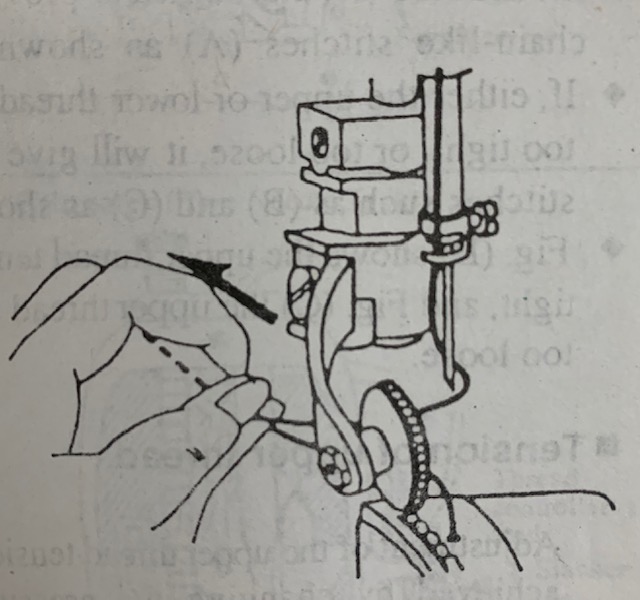
- If the upper and lower thread tension are well balanced, the two threads will link together in the middle of the fabric to provide perfect chain-like stitches (A) as shown in Fig.
- If, either the upper or lower thread tension is too tight, or too loose, it will give imperfect stitches such as (B) and (C) as shown in Fig.
- (B) shows the upper thread tension is too tight, and Fig. (C) the upper thread tension is too loose.
Tension of upper thread
Adjustment of the upper thread tension can be achieved by changing the pressure of the tension discs of the regulator, as well as the strength and operating range of the thread take-up spring. In case of One Needle Type
- Pressure of the thread ‘tension discs.
- For general fabric stitching the desired tension can be obtained just by adjusting the pressure of the tension discs.
- To strengthen, turn the thread tension nut to the right.
- To slacken, turn to the left.

In case of Two Needle Type
- To strengthen the pressure of thread tension discs, turn the thread tension nut to the right.
- To slacken, turn the tension nut to the left.
- Strength of the thread takes up spring.
- Adjust the strength of the take-up spring according to the materials to be stitched.
- Standard materials…approx. 25g.
- Light materials (small stitch length)
- Heavy materials (large stitch length) strengthen the spring…; approx. 30g.

How to adjust
- Leave the presser bar lifter down.
- Remove the face plate.
- Loosen the small screw inside of the face plate as shown of the upper thread tension regulator (one needle type) or of the thread tension controller (two needle type).
- Fit the screwdriver into the groove of the thread tension stud, or thread controller stub, and turn the stud to the left to strengthen, and to the right to slacken.
After adjusted, tighten the small screw, and put the face plate back on.


3) Operating range of the thread takes up spring
- To obtain proper working conditions, it is necessary to adjust the strength of the take-up spring as well as change the operating range of the take-up spring.
- The operating range can be measured when the take-up lever is at the highest position, and when the upper thread is pulled, and the tension spring moves within the width of 8mm, it is considered as standard.
- In the case of standard (general fabrics) materials. ……approx. 8mm (5/16″)
- In case of light (small stitch length) materials. increase the operating range slightly… ……approx. 8mm (5/16″) or up
- In case of heavy (large stitch length) materials. decrease the operating range slightly… ……approx., 8mm (5/16″) or less

How to adjustment (One Needle Type)
- Lower the presser bar lifter.
- Loosen the thread tension regulator set screw.
- Fit the screwdriver into the groove of the tension regulator stud; and turn the stud to the right to small the operating range.
- Turn the stud to the left to large the operating range.
- After adjusted, tighten the screw.
How to adjust (Tow Needle Type)
- Loosen the thread controller set screw.
- Fit the screwdriver into the groove of the thread controller stud and turn the stud to the right to small the operating rang.
- Tum the stud to the left to range the operating range.
- After adjusted, tighten the screw.

■ Tension of lower thread.
There is virtually no need to adjust the lower thread tension, except for special kinds of fabrics or thread. when slight adjustment will be necessary.
- Turn the balance wheel by hand and stop when the thread take-up lever comes down to its lowest position.
- Move the slide plate so that you find the thread tension screw of the hook base.
- Fit the screwdriver into the hole (A) of the hook shaft bracket as shown in Fig Turn the tension screw to the right to strengthen the thread tension.
- Turn the screw to the left to weaken the thread tension.


4. ADJUSTMENT OF FEED DOG HEIGHT AND PRESSURE OF PRESSER ON MATE RIALS. The feed dog height and pressure of presser on materials must be properly adjusted according to the materials to be sewn.
- In case of light materials: The material may be damaged if the feed dog is raised excessively or the pressure of presser on materials is too strong.
- In case of heavy materials: It will not make uniform stitching if the feed dog is not raised properly, or the pressure of presser is too weak.
- In the case of light materials…. approx. 0.8mm in height
- In case of general fabrics…approx. 1.0mm in height
- In case of heavy materials……… approx. 1.2mm. in height
- The height of feed dog is measured when the feed dog is raised to its highest position from the surface of needle plate turning the balance wheel by hand

Adjustment of feed dog height
- Lay down the machine bed toward the other side.
- Remove the gear box.
- Turn the balance wheel by hand and stop when the feed dog is raised to its highest position from the surface of needle plate.
- Loosen the screw of feed lifting rock shaft crank.
- Adjust the feed dog to the desired height moving the feed lifting rock shaft crank back and forth as per an arrow shown in Fig.
- After adjusted, tighten the screw of feed, lifting rock shaft
Adjustment of pressure of presser foot
- Turn the presser regulating thumb screw to the right to strengthen the pressure of presser foot.
- Turn the screw to the left to loosen the pressure of presser foot.
- PROPER TIMING BETWEEN THE HOOK AND ENEEDLE
Place and adjust the hook in the condition described below in case the thread gets entangled in the hook, or when its position is changed due to shock, or other causes, or when it is replaced with new a one.

How to remove the hook:
- Turn the balance wheel by hand and stop when the thread takes up lever comes down to its lowest position.
- Remove the slide plate, then take out the bobbin.
- Remove the needle plate.
- Remove the hook cover plate (front) (In case of two needle type, remove the hook cover plate (upper) both the front and back.)
- Remove the hook opener screw, and then remove the opener.
- Loosen the hook gib screw and remove the hook gib fixed in front of the hook body as shown in Fig.
- Hold the latch lever up turning it slightly so that it can be taken out.
- Remove the hook body center set screw so that it can be taken out.

How to place the hook:
- Place the hook in backward order from removing procedure.
- When placing the hook body, remember to place it at the same position as it was taken out.
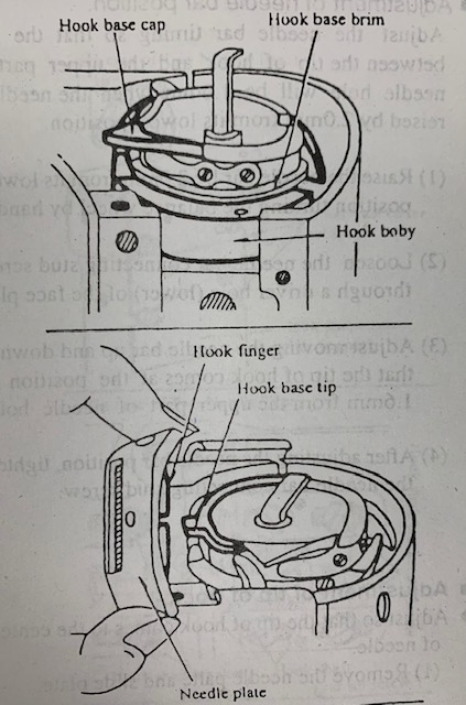
- When inserting the hook base hold the hook base cap turning it to the left as shown in Fig. And fit the hook base brim into slot of the hook body on the inside of the other side.
- When placing the needle plate, place the needle plate adjusting the hook base so that the tip of hook base fits into the hook finger of the needle plate as shown in Fig.
The position of the hook and needle:
As shown in the Fig. When the needle raised is 2.0mm from its lowest position of the needle, the hook and needle should be as follows.
- Upper part of the needle hole. ……Lower by 1.6mm from the tip of hook.
- Tip of hook……At center of needle.
- Gap between tip of hook and lateral face of needle. by 0.05mm.
- Adjustment of the relative position of the hook and needle can be done as follows:
- Move the roller foot to the left, remove the needle plate for easy adjustment.


Adjustment of needle bar position
Adjust the needle bar timing so that the gap between the tip of hook and the upper part of needle hole will be 1.6mm when the needle is raised by 2.0mm from its lowest position.
- Raise the needle bar by 2.0mm from its lowest position turning the balance wheel by hand.
- Loosen the needle bar connecting stud screw through a driver hole (lower) of the face plate.
- Adjust moving the needle bar up and down so that the tip of hook comes at the position by 1.6mm from the upper part of needle hole.
- After adjusting the needle bar position, tighten the needle bar connecting stud screw.
Adjustment of tip of hock
Adjust so that the tip of hook comes to the center of needle.
- Remove the needle plate and slide plate.
- Lay down the machine head toward the other side.
- Remove the gear box.
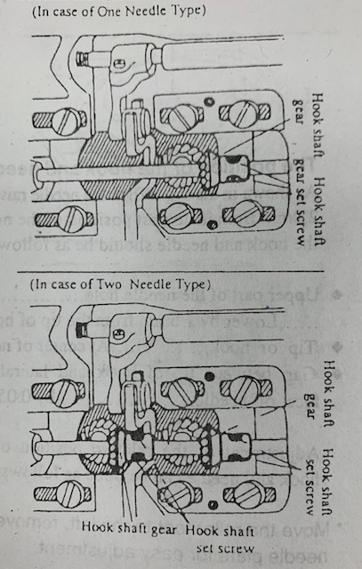
- Loosen the two set screws of the hook shaft gears.
- Turn the balance wheel by hand and stop when the needle is raised 2.0mm from its lowest position.
- Turn the hook by hand, enabling the tip of hook to come to the center of needle.
- After adjusting, tighten the two set screws of the hook shaft gears.
- Place the gear box.

Adjust that the gap between the tip of hook and lateral side of the needle to come to 0.05mm.
In case of 1-needle, there is virtually no need to adjust it. However, in case of 2-needle, it is necessary to adjust it when changing the needle gauge sizes.
- Loosen the screws of the hook post cover plate (front and back).
- Lay down the machine head toward the other side.
- Remove the gear box.
- Loosen the hook shaft gear set screws.
- Loosen the set screws of hook shaft bracket. (6) Turn the balance wheel by hand and stop when the needle is raised by 2.0mm from its lowest position.
- Turn the hook by hand and bring the tip of hook to the center of needle.
- Move the hook shaft bracket to the right and left, so that the gap between the tip of hook and lateral side of needle is 0.05mm.
- After adjusting, tighten the set screws of hook shaft gear and bracket.
- Place the gear box.
- PROPER TIMING BETWEEN THE HOOK AND OPENER.
- Remove the slide plate.
- Turn the balance wheel by hand and stop at the position where the opener and the needle plate are furthers point apart.
- Check whether the gap between the part of hook base (A) and the opener is approx. 0.2mm as shown in Fig. (there is a slight difference according to the thread to be used)
- In case the gap is too wide or narrow, adjust it fitting the screwdriver into a driver hole (B) of the hook shaft bracket, then loosen the opener adjustable screw and moving the opener to the right or left.
- After adjustment, tighten the opener adjustable screw.


- PROPER TIMING BETWEEN THE FEED DOG AND NEEDLE
The proper timing of the feed dog and needle will be when the material is fed through and he needle boa up reach to the needle plate surface, just now the feed dog begins to sink downward through the needle plate surface as shown in Fig.
This adjustment is based on the Feed dog height is at 1.0mm.
- Loosen the arm side cover thumb screw.
- Move the side cover to the right, and open to upper side as shown in Fig.
- Loosen the set 2-screws of the feed lifting cam. q
- While holding the feed lifting cam by hand, turn the balance wheel toward your side so that the feeding device will be faster.
- To slow the feeding device, turn the balance wheel toward the other side.
- After adjustment, tighten the set screws of the feed lifting cam.
- CLEANING AND LUBRICATION Cleaning: The teeth of feed dog, hook, upper thread tension regulator discs, and thread controller discs are often covered by dust and lint causing improper operation and uneven stitching. Therefore, clean as often as necessary.
- Lubrication: Lubrication is one of the most important phases of the machine maintenance. With improper lubrication, excess abrasion of machine pails will cause to shorten the life of the machine, Therefore, lubricate in the order as follows:
- The number of times for lubrication.
- Usual working……at 2-3 times per week.
- Continuous working, every day…once each
- Volume of lubrication:
- Place o……. marked approx. 5 cc or more
- Place mm… marked approx. 5-6 drops
- Place ……… marked approx. 1-2 drops
- Places where to lubricate.
Lubricate the places where arrow is shown in Fig. (on right)

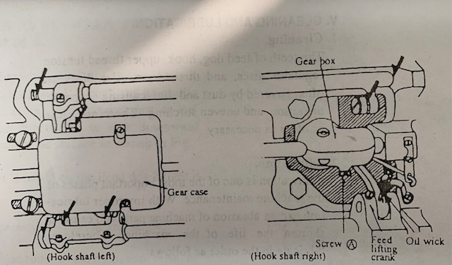
Since the oil wick connected with the lifting crank for the right side of hook shaft is worked to flow oils, penetrate oil fully before by 20 working (if the oil wick is not penetrated with oil, it has no effect to flow oil).
- Grease
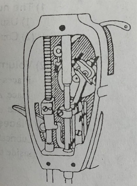
- Remove the oil hole screws (A) & (B), of the gear box fixed to arm and hook shaft, then grease into the holes periodically.
- Remove the gear case of the left side of hook shaft, then also grease into the gears sufficiently.
